Explore our comprehensive range of analysis crafted by passionate experts with over two decades of experience.
The Freshest. Chemical-Free.
Quis habitant dignissim enim facilisis in at eget vitae pulvinar ipsum in felis aenean enim morbi sit in elementum tincidunt mi non justo semper tincidunt bibendum porta ipsum a ipsum et ornare habitant mattis augue nulla faucibus varius risus, non.
Quam id vitae, mi ac a purus facilisi dignissim nibh dui in egestas fusce tristique nisi sed integer porttitor nibh est quis urna mauris euismod nunc ac commodo sed vivamus est dui pellentesque non quis nulla sed amet ut rhoncus.
Chemical-Free
Ultricies mattis sit iaculis in.
Fresh & Healthy
Eget lacus facilisi enim nec.
100% Organic
Lacinia nisl arcu adipiscing.
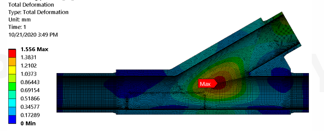
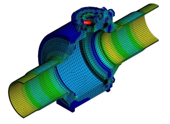
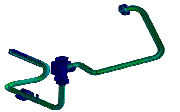
Fitting – total deformation check Analysis page
Girth welded fitting analysed for installation load case, operational & seismic load case to understand the capability of the intersection area against ASME BPVC VIII Div 3 . External forces – Fx, Fy, Fz & External moment Mx, My, Mz considered for the load case for installation load as both branch connection have to uplift the entire structure weight. Welding integrity verified at both joints considering the residual stresses Pipeline code is DNV F101, the allowable strain is considered as max 1% for this case between pipeline and component level
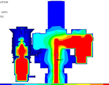
Thermal analysis
Thermal analysis performed on tree block to flow module to understand the temperature distribution across the flowpath
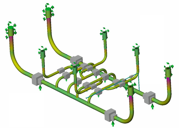
Piping
Global analysis performed using AUTOPIPE. Load cases derived based on actual sequence i.e
FAT
Transportation
Lifting
Splash zone
Landing
Pressure test
Installation
Operation
Seismic
Buckling
Basis for piping analysis is based on ASME B31.8 & Buckling analysis is based on DNV OS F101
Connection
Structural assessment performed on flange connection based on ASME BPVC SEC VIII Div 2, Part 5 to predict the stresses at bolt preload condition and also the functional assessment performed to check the sealing integrity.
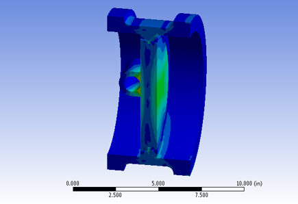
Trunnion mounted ball valve
FEA performed on valve pressure containing part based on two condition Hydrostatic test Design condition.
Failure mode is set as plastic collapse. The load factors are based on ASME BPVC VIII Div 2 which ranges between 1.68 to 2.4 based on the above condition.
...
Equivalent stress plot in triple offset butterfly valve to check the disc thickness sufficient for intended loading condition. In addition pressure distribution between the disc & body to verify the sealing performance against differential pressure.
...
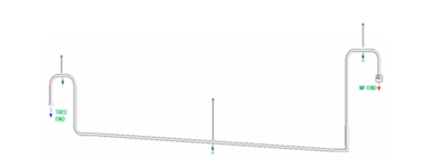
Jumpers are components designed to connect between tree & manifold. Installation of jumpers is based on metrological survey after the tree & manifold is load out, hence deflection study of jumpers is important to avoid clash and smooth installation process
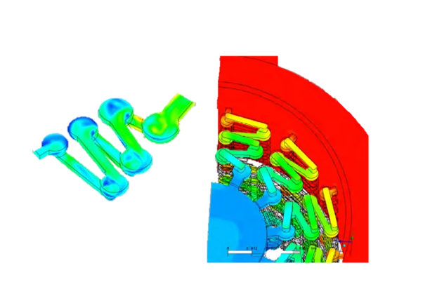
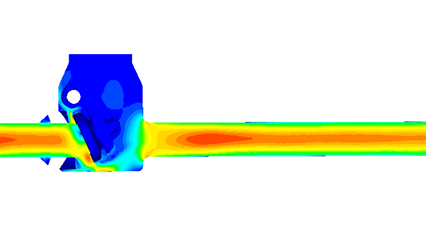
CFD - choke trim
Gas wells operate at pressure above 10000psi experience high pressure differential(∆P) due to choked flow. Difference in area generates dynamic waves which causes noises. Multi stage trims are used to have reduced noise level. Mach number analysed considering the velocity profiles, turbulent flow regime and dynamic waves to keep the noise level low as possibleJumpers are components designed to connect between tree & manifold. Installation of jumpers is based on metrological survey after the tree & manifold is load out, hence deflection study of jumpers is important to avoid clash and smooth installation process
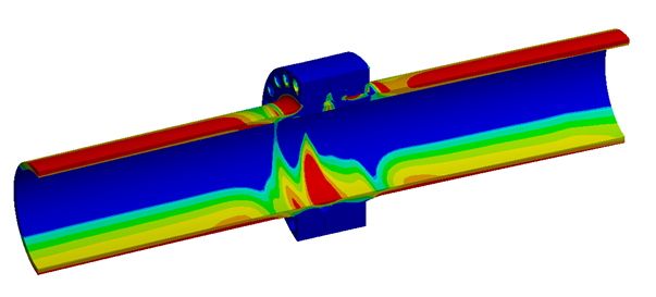
CFD – Flow loop
Flow loops are prone to erosion. CFD shall be used to predict hotspot points based on intricate geometry and also the depth. This can be the input to the FEA for stress evaluation. This would be the most accurate and conservative approach in avoiding premature failures. Deflections shall be predicted to avoid interference with other components
CFD – Check valve
Study performed to evaluate the valve flow characteristics @ various flow rates. Project flow rates are driven by Customer. Disc position/opening angle determined based on the Min & Max BPD from the reservoir. In addition valve capacity verified at reverse flow condition. Min cracking pressure shall be determined based on required flow rate
...
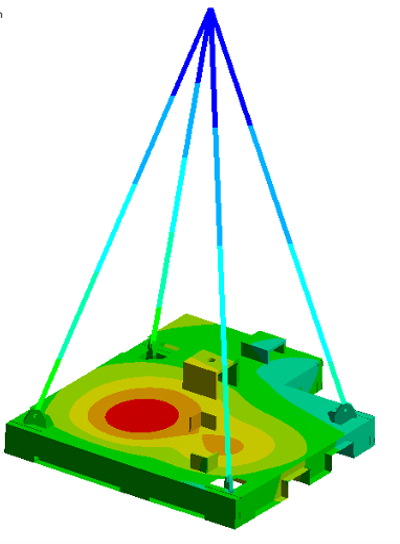
Lifting analysis done as per DNV ST 2.7. Load applied as point mass with acceleration factor applied, stress plot and deflection verified